1970 And Earlier Adjustments
1979 To 1984 Adjustments
1971 TO 1978 CLUTCH ADJUSTMENT**
GENERAL
Periodic adjustment of the clutch is required every 2000
miles to compensate for lining wear. The need for attention
to clutch and controls will also be indicated by the clutch
slipping under load, or dragging in released position. In any
case, the first thing to be checked is the adjustment of
clutch controls.
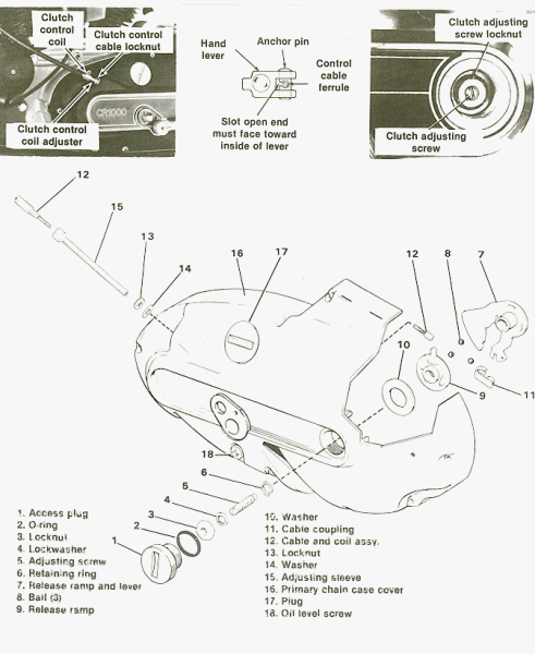
ADJUSTING CLUTCH RELEASE MECHANISM
(Figure 4-3)

1. Loosen control coil adjuster locknut (13) and turn
adjuster (15) inward until there is a large amount of free
play at hand lever on handlebar.
2. Remove access plug (1) from primary chain compartment cover.
3. Loosen adjusting screw locknut (3) and turn screw (5)
inward until it becomes harder to turn (starts to release the
clutch) and continue turning (about 2 more turns) to be sure
clutch is disengaged.
4. Adjust all free play out of control cable by turning adjuster
(15) Outward. Do not put any tension on cable. With
aH slack in cable eliminated (no play at hand lever) tighten
the coil adjuster locknut (13). This is the correct cable adjustment.
5. The clutch release adjustment should then be made with
the clutch adjusting screw as follows: Loosen the locknut
(3) and back off the adjusting screw (5) until the clutch is
engaged (screw turns easier), then turn screw inward until the
point where free play has just been eliminated. From this
point, turn the adjusting screw outward 1/4 to 1/2 turn to
establish correct free play, and tighten locknut. Check cable
free play at clutch hand lever. Hand lever should have 1/8
free play. If incorrect, adjust sleeve and tighten locknut.
If the clutch continues to slip under load or drag in released
position, clutch springs may need adjusting or release
mechanism may be defective.
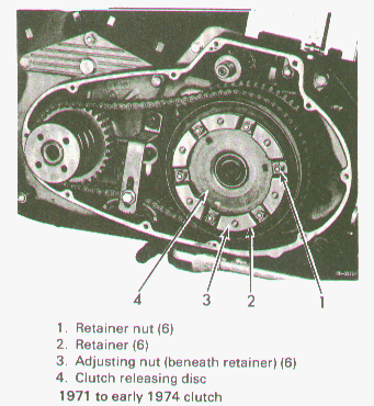
ADJUSTING CLUTCH SPRING TENSION (1970 TO EARLY
1974 MODELS)
(Figure 4-8)
CAUTION
On Electric Start XLH Models, remove battery
cover and disconnect ground wire from battery (-)
terminal to prevent accidental starter operation.
Remove left footrest and rear brake foot lever. Place an oil drain pan
under clutch and remove front chain cover screws,cover
and gasket.
With cover removed, the clutch releasing disc (4), six spring
tension adjusting nuts (3), stud retainers (2) and retainer
nuts (1) are in view.
If required, adjust each of the six nuts one half turn at a time
after removing retainer nuts (1) and retainers.
Tightening the spring tension adjusting nut moves the
releasing disc closer to the outside surface of the outside surface
of the outer drive plate. This increases the clutch spring pressure on the
clutch plates through pressure plate studs.
Outer surface of releasing disc should measure 11/32 in.
from the outer surface of the outer drive plate for normal
clutch spring tension adjustment.
When increasing spring tension, do not diminish above
distance to less than 5/16 in. or clutch may not release.

ADJUSTING CLUTCH SPRING TENSION (LATE 1974 AND
LATER MODELS)
Clutch spring tension is determined by the length of six stud
spacers. To correct clutch slippage
caused by worn clutch drive plate linings, a set of shorter
than standard spacers can be installed.
Under no circumstances should clearance between
releasing disc and outer drive plate be allowed to go under
minimum 1/8 in. dimension shown. All spacers should be
equal in length.
Return to Clutch Index
**Copyright © 1970,1973,1985 Harley Davidson, Inc.


