ADJUSTING THE CLUTCH ON PANHEADS**
Foot Clutch Control Adjustment
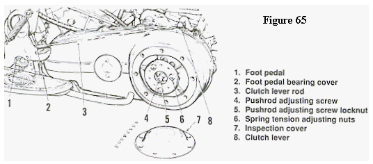
Refer to Figure 65 for this procedure
1. Disengage the clutch by pushing the foot pedal all
the way down (heel down). Check that the clutch
lever just touches the transmission cover. If not,
adjust the clutch lever as follows:
a. Loosen the clutch lever rod locknuts and turn
the lever rod adjuster to lengthen or shorten
the rod so that the rod just clears the foot pedal
bearing cover. The rod should not be bent
down by the bearing cover.
b. Tighten the locknut and recheck the clutch
lever rod position.
2. Remove the screws securing the clutch adjustment
cover and remove the cover.
3. Move the foot pedal to the fully engaged position
(toe down).
4. Loosen the pushrod adjusting screw locknut. Then
turn the pushrod adjusting screw so that the end of
the clutch lever has approximately 1/8 in. (3.17 mm)
free play before the clutch disengages. After making
this adjustment, check the following:
a. On 1964 and earlier models, the clutch lever
should contact the transmission case cover.
b. On 1965 models, there should be 1/4 in. (6.35
mm) clearance between the clutch lever and
the starter drive housing.
5. Install all parts previously removed.
6. Test ride the bike. If the clutch slips after making
this adjustment, perform the Clutch Spring Tension
Adjustment.

Hand Clutch Booster Adjustment
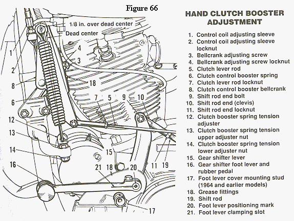
Check the booster adjustment when the clutch
hand lever operation becomes difficult, or if improper clutch operation is indicated. Refer to Figure
66 for this procedure.
1. Loosen the clutch lever rod locknut.
2. Adjust the clutch lever rod so that the clutch
release lever has approximately 1/2 in. (12.7 mm)
free movement. Move the lever forward until all
slack in mechanism is taken up.
3. On 1964 and earlier models, the distance between
the outer edge of the chamfered slot in lever and foot
shifter housing on the transmission should be 4 1/4
in. (10.8 cm). On 1965 models, the distance between
the chain housing and clutch lever rod should be 1/4
in. (6.35 mm).
4. Remove the clutch inspection cover or the chain
cover.
5. Loosen the pushrod screw locknut.
6. Turn the pushrod adjusting screw as required to
obtain the clearance specified in Step 3 for your
model.
7. Tighten the locknut.
8. Loosen the control coil adjusting sleeve locknut.
9. Turn the adjusting sleeve until there is approximately I in. (25.4 mm) free play at the clutch hand
lever.
10. Loosen the bellcrank adjusting screw locknut.
11. Turn the bellcrank adjusting screw until the
bellcrank does not cross dead center when moved
back and forth by hand.
NOTE
Dead center is indicated in Figure 66
12. Loosen the upper adjuster nut as far as it will go.
13. Turn the bellcrank adjusting screw a little a time
until the bellcrank moves over dead center and remains in that position when released. Do not move
bellcrank with clutch lever, move it by hand. Bell-
crank should lock in position approximately 1/8 in.
(3.17 mm) past dead center.
14. Tighten the bellcrank adjusting screw locknut.
15. Adjust the clutch lever rod so that there is 1/16
in. (1.58 mm) free movement of the clutch activating
lever.
16. Tighten the clutch lever rod locknut.
17. Turn the control coil adjusting sleeve until there
is 1/2 in. (12.7 mm) free movement of the clutch
hand lever before clutch starts to disengage.
18. Tighten the control coil adjusting sleeve locknut.
19. Pull the clutch hand lever in fully. Then tighten
the adjuster nut until the lever remains in. Next,
slowly loosen the adjuster nut until the clutch hand
lever returns to its released position.
20. Tighten the adjuster nut (13, Figure 66).
21. Test ride the bike. If the clutch slips after making
this adjustment, perform the Clutch Spring Tension
Adjustment in this chapter.
Clutch Spring Tension Adjustment
If the clutch slips after adjusting the foot or
booster clutch assembly, you can increase spring
tension on the 3 clutch springs up to a certain point.
NOTE
Do not use this adjustment procedure to
compensate for worn or damaged parts
1. Remove the clutch inspection cover (Figure 65).
2. Measure the distance from the inner edge of the
spring collar to the outer disc surface. Interpret
results as follows:
a. If this distance is equal to or less than 7/8 in.
(22.2 mm), the clutch springs are adjusted at
their maximum setting. If the clutch is slipping, disassemble
the clutch and inspect the plates for wear
or oil contamination.
b. If this distance is greater than 7/8 in. (22.2
mm), perform Step 3.
NOTE
A new clutch is set up with a spring
collar to outer disc surface distance of
31/32 in. (24.6 mm).
3. Tighten the 3 adjusting nuts 1/2 turn each. Then
test the clutch by starting the engine and shifting the
transmission into gear. Do not increase the spring
tension so far that the measured distance is 7/8 in.
(22.2 mm) or less.
4. Install the cover.

Return to Clutch Index
**Copyright © 1992 Intertec Publishing Corporation


